Nylon Insert Lock Nuts Price - Din2510 Double End Studs with Reduced Shank with Hexagon Nuts – Dingshen Metalworks
Short Description:
Din2510 Double End Studs with Reduced Shank with Hexagon Nuts Standard: Din 2510 Form L, Z, K, ZU/KU, GP, GQ, GR, GS, HP, HQ,NF, TF, AF/AFO, BF/BFO Metric Thread Size: M12-M100 with various lengths Available Material or Grade: ASTM 193/320 B7, B7M, L7, L7M, B16, B8, B8M, B8T CL1&CL2 ASTM 194 2H, 2HM, 4, 7, 7M, 8, 8M ASTM A453 660 ISO 898-1 5.8, 6.8, 8.8, 10.9, 12.9 1.1181 / C35E 1.1191 / C45E 1.7218 / 25CrMo4 1.7225 / 42CrMo4 1.7709 / 21CrMoV5-7 1.7711 / 40CrMoV4-6 1.7729 / 20CrMoVTiB4-10...
Product Detail
Product Tags
Nylon Insert Lock Nuts Price - Din2510 Double End Studs with Reduced Shank with Hexagon Nuts – Dingshen Metalworks Detail:
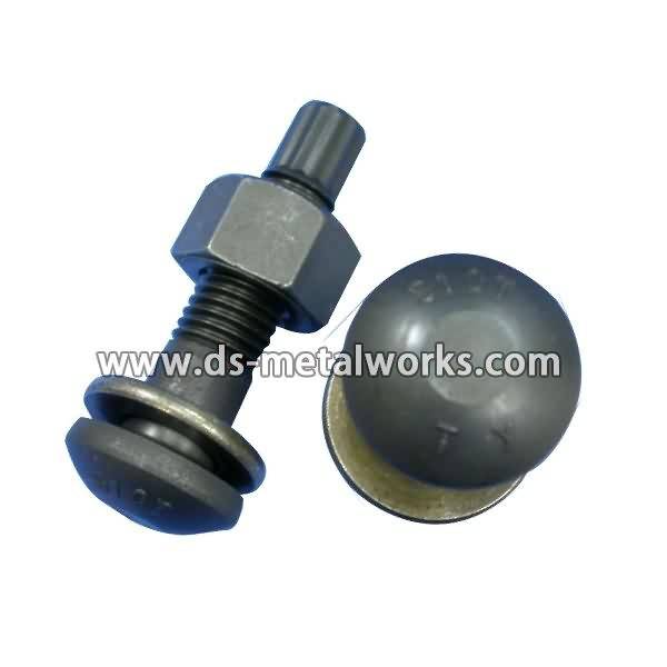
Din2510 Double End Studs with Reduced Shank with Hexagon Nuts
Standard: Din 2510 Form L, Z, K, ZU/KU, GP, GQ, GR, GS, HP, HQ,NF, TF, AF/AFO, BF/BFO
Metric Thread Size: M12-M100 with various lengths
Available Material or Grade:
ASTM 193/320 B7, B7M, L7, L7M, B16, B8, B8M, B8T CL1&CL2
ASTM 194 2H, 2HM, 4, 7, 7M, 8, 8M
ASTM A453 660
ISO 898-1 5.8, 6.8, 8.8, 10.9, 12.9
1.1181 / C35E
1.1191 / C45E
1.7218 / 25CrMo4
1.7225 / 42CrMo4
1.7709 / 21CrMoV5-7
1.7711 / 40CrMoV4-6
1.7729 / 20CrMoVTiB4-10
1.4913 / X19CrMoNbVN11-1
1.4923 / X22CrMoV12-1
1.4980 / X6NiCrTiMoVB25-15-2)
1.4986 / X7CrNiMoBNb16-16
Inconel 625, Inconel 718, Duplex, SuperDuplex
Finish: Plain, Black Oxide, Zinc Plated, Zinc Nickel Plated, Cadmium Plated, PTFE etc.
Packing: Bulk about 25 kgs each carton, 36 cartons each pallet
Advantage: High Quality and Strict Quality Control, Competitive Price,Timely Delivery; Technical Support, Supply Test Reports
Please feel free to contact us for more details.
Product detail pictures:


Having a sound small business credit score, outstanding after-sales services and modern manufacturing facilities, we've got earned an fantastic reputation among our buyers across the globe for Nylon Insert Lock Nuts Price - Din2510 Double End Studs with Reduced Shank with Hexagon Nuts – Dingshen Metalworks, The product will supply to all over the world, such as: San Francisco, Bangladesh, Lahore, With the development and enlargement of mass clients abroad, now we have set up cooperative relationships with many major brands. We have our own factory and also have many reliable and well-cooperated factories in the field. Adhering to the quality first, customer first, We are provideing high-quality, low-cost products and first-class service to customers. We sincerely hope to establish business relationship with customers from all over the world on the basis of quality, mutually benefit. We welcome OEM projects and designs.
Tools you’ll need:
8 mm socket with small ratchet
10 mm socket with medium ratchet
10 mm wrench
19 mm socket
18 inch or longer breaker bar
Rotor holder wrench
Torque wrench (5 to 130 ft * lbs)
Online directions that I used are here:
https://www.leftcoastklrs.com/balancer_lever_upgrade.htm
https://www.leftcoastklrs.com/Install_a_torsion_spring.htm
I got all the parts for this job from Eagle Manufacturing & Engineering: https://eagle-m-e.com/
I drained the oil to replace the doohickey. I can’t say from firsthand experience if this is the easiest or best way.
This was my first time dooing the doo. I’ve put about 1000 miles on the bike since with no problems. I’d call it a successful installation.
Instructon will be succint due to text limitations.
Remove the skid plate (three 10 mm bolts (2008: four 10 mm bolts).
Remove the shift lever (one 10 mm bolt. Use the wrench).
Remove the counter sprocket cover (three 10 mm bolts).
If you drained the oil, PUT THE OIL PLUG BACK AND TORQUE IT TO 17 (2008: 21) FT * LBS NOW!
Gently unplug the green neutral wire and wiggle the wire out of the channel forward of the front sprocket. It will help if you get the wires free of the clip behind where the sprocket cover was.
Remove the ten 8mm outer left side cover bolts.
Carefully and as evenly as possible, pull the outer side cover off. There are strong magnets attatched to the cover, don’t be afraid if the cover hops to the side a little. Leave the wires going into the cover alone. Hang the cover from wire from over the seat (or however you want. Whatever works for you).
Remove the starter cluster gears (two sets).
Use the rotor holder wrench, 19 mm socket and breaker bar to break the rotor holder bolt loose – go counterclockwise (anticlockwise for you crazy Brits). It should have been torqued to 130 ft * lbs… put some muscle into it. Be sure the head of the rotor holder wrench is lined up nicely with the rotor, or it will probably jump off. It took me a few tries to get it at the right angle.
Use the (greased) rotor puller and screw it into where the rotor holder bolt was. Same tools as the rotor bolt, but other direction.
Remove the puller. Turn the crank so the groove in the threads is up. If you don’t, the woodruff (half moon) key might jump out and run away. Remove the rotor and starter gear. It might be easier if you remove them separately (it was for me). Be aware of the washer that is in front of the gear. There are also two thick washers.
Remove the doohickey adjustment bolt. Remove the doohickey.
Remove the nine 8 mm bolts holding the inner side cover on. The one inside the case is shorter than the rest.
Pull the cover off evenly. Use your thumb to keep the doohickey’s perch in place.
Torsion spring: drill hole in aft quadrant of inner cover with supplied drill bit. Remove the coil spring. Leave the lever as a spacer. Website 2.
Coil spring: replace the stock with the new one. Try the longer one first. Website 1.
Put the inner cover back in place (new gasket if old one’s bad). You shouldn’t need sealant. Torque the bolts to 69 in * lbs (almost 6 ft * lbs).
If you’re using the torsion spring, push that against the inner cover as far as it will go.
Slide the new doo in place.
Torsion spring: push the bottom of the doo to the left (clockwise) and tighten the adjustment bolt. Latch the end of the spring into the slit in the doo. Push the spring all the way onto the doo. NO PLIERS! Use a screw driver. Website 2.
Loosen the adjustment bolt and retighten to “snug.” For ’87 – ’95 and ’08, put the supplied washer on the adjustment bolt before reinstalling as they don’t have a washer (accuracy check, please!)
Oil everything from here on out, except the tapered part of the crank and the inner part of the rotor. Install the twoo thinck washers, the big starter gear, the big thin washer, the woodruff key, and the rotor. Spin the starter gear clockwise as you push the rotor on.
Install a new rotor bolt. Torque it to 85 ft * lbs, loosen it slightly, torque it to 130 ft * lbs. Website 1.
Install the two starter cluster gears. Make sure you have all four washer in place.
It is easier if both dowels are on the engine. Install a new (if the old one is bad) gasket and the outer side cover. Encouragement may be necessary to get the cover all the way on. Lightly tap with your fist. DON’T USE A HAMMER!
Put the out cover bolts back on and torque to 69 in * lbs. Put the rubber grommet back over the adjustment bolt.
If you drained the oil, PUT 2.5 L IN NOW!
Reinstall the sprocket cover, the shift lever, and the skid palte. And you’re done!
Please rate and leave comments!
For a wealth of KLR 650 information, please visit KLR650.NET – Your Kawasaki KLR650 Resource!
If you decide to join, please use my referral link: https://www.klr650.net/forums/index.php?referrerid=17746